Amplifier of Hi-Fi channel
Take 15 minutes to prepare this exercise.
Then, if you lack ideas to begin, look at the given clue and start searching for the solution.
A detailed solution is then proposed to you.
If you have more questions, feel free to ask them on the forum.
A stereo amplifier can be modeled by the following circuit diagram in which the input resistance \(R_e\) will be considered infinite :
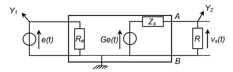
It performs the following two tests :
Test n°1 :
\(e(t) = Ecos(2\pi ft)\), \(R = 16\; \Omega\), RMS \(e(t)\), \(1 \;mV\).
Is measured with a digital oscilloscope effective (RMS) output value equals to \(0,67 \;V\).
Test n°2 :
\(e(t) = Ecos(2\pi ft)\), \(R = 8\; \Omega\), RMS \(e(t)\), \(1 \;mV\).
We then measure the effective (RMS) output value equals to \(0,5\; V\).
Moreover, we find that during each test, the two output signals keep, regardless of the frequency, the same effective (RMS) value and are in phase with \(e(t)\).
Question
Determine the gain \(G\) and the complex output impedance \(Z_s\).
Solution
We denote, in complex notation and noting \(E_e\) and \(V_{s,e}\) effective (RMS) values of the input and output voltages and \(\varphi\) the phase shift of \(v_s\) with respect to \(e\) :
\(\underline e (t) = {E_e}\sqrt 2 \exp (j2\pi ft)\)
And :
\({\underline v _s}(t) = {V_{s,e}}\sqrt 2 \exp (j(2\pi ft + \varphi ))\)
The voltage divider rule gives :
\({\underline v _s} = \frac{R}{{R + {{\underline Z }_s}}}G\;\underline e\)
By denoting :
\({\underline Z _s} = {R_s} + j{B_s}\)
Where the real and imaginary parts \(R_s\) and \(B_s\) a priori depend on the frequency, the effective value of the output voltage can be written :
\({V_{s,e}} = \frac{R}{{\sqrt {{{(R + {R_s})}^2} + B_s^2} }}G\;{E_e}\)
With, in addition :
\(\tan \varphi = - \frac{{{B_s}}}{{R + {R_s}}}\)
The phase shift between \(v_s\) and \(e\) is zero being regardless of the frequency, and deduce \(B_s=0\) and :
\({V_{s,e}} = \frac{R}{{R + {R_s}}}\;G{E_e}\)
As the effective (RMS) value \(V_{s,e}\) does not depend on the frequency, the output of the stereo impedance is finally real and equivalent to a single resistor of constant value \(R_s\) , independent of frequency.
Tests with two resistance \(R\) values then lead to the system of two following equations :
\((16 + {R_s})0,67 = {16.10^{ - 3}}\;G\)
And :
\((8 + {R_s})0,5 = {8.10^{ - 3}}\;G\)
With \(R_s\) in \(\Omega\).
The resolution leads to :
\({R_s} = 8\;\Omega\) and \(G=10^3\)
Question
The amplifier being supplied with a voltage :
\(e(t) = E cos (2\pi ft)\)
What should be the load resistor \(R\) so that it provides the maximum average power at the constant amplitude input voltage \(E\) ?
Solution
The average electrical power received by the load resistance is equal to :
\(P = \frac{1}{R}V_{s,e}^2 = \frac{R}{{{{(R + {R_s})}^2}}}{G^2}E_e^2\)
It will be extremal, at given \(E_e\), \(G\) and \(R_s\) (amplifier characteristics) when :
\(\frac{{dP}}{{dR}} = 0\)
But :
\(\frac{{dP}}{{dR}} = {G^2}E_e^2\frac{{{{(R + {R_s})}^2} - 2R(R + {R_s})}}{{{{(R + {R_s})}^4}}} = {G^2}E_e^2\frac{{{R_s} - R}}{{{{(R + {R_s})}^3}}}\)
Therefore :
\(\frac{{dP}}{{dR}} = 0\) if \(R=R_s\).
The power is then effectively maximum and is equal to :
\({P_{\max }} = P({R_s}) = {G^2}E_e^2/4{R_s}\)
The load resistance is called adapted to the output resistance of the stereo and we talk about adaptation of resistors.