The voltage and current dividor
Fondamental : Networks and dipoles
A network is a complex electrical circuit formed of conductive wire and components connected to the outside by two terminals (dipoles).
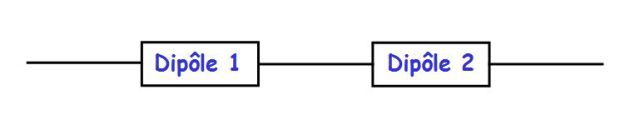
Dipoles may be placed in series :
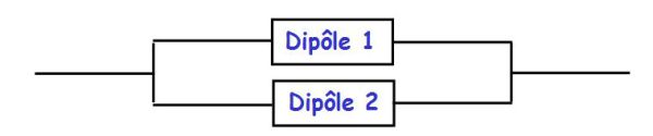
Or in parallel (in derivation) :
Fondamental : Loop, branch and node
Node : a network node is an inter-connection point connected to at least three dipoles.
Branch : a branch is a circuit portion between two nodes. It can include one or more dipoles in series.
Loop : a loop is a set of branches, forming a closed loop, which passes only once by a given node.
Fondamental : Voltage Divider
The voltage divider is defined in the following figure :
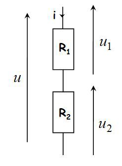
Tensions \(u_1\) and \(u_2\) are expressed in terms of the voltage \(u\) applied across the two resistors placed in series :
\(\left\{ \begin{array}{l}{u_1} = \frac{{{R_1}}}{{{R_1} + {R_2}}}u \\{u_2} = \frac{{{R_2}}}{{{R_1} + {R_2}}}u \\\end{array} \right.\)
Fondamental : Current divider
The current divider is defined in the following figure :
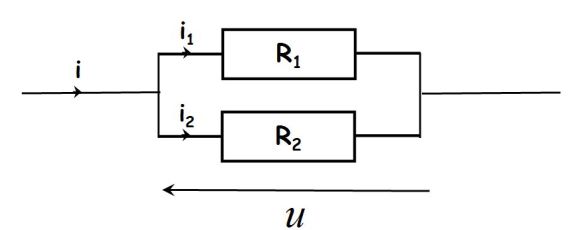
Currents \(i_1\) and \(i_2\) are expressed in terms of current \(i\) that arrives in the two resistances placed in parallel :
\(\left\{ \begin{array}{l}{i_1} = \frac{{{G_1}}}{{{G_1} + {G_2}}}i \\{i_2} = \frac{{{G_2}}}{{{G_1} + {G_2}}}i \\\end{array} \right.\)
Or :
\(\left\{ \begin{array}{l}{i_1} = \frac{{{R_2}}}{{{R_1} + {R_2}}}i \\{i_2} = \frac{{{R_1}}}{{{R_1} + {R_2}}}i \\\end{array} \right.\)
Conductances \(G_i\) are given by :
\(G_i=\frac{1}{R_i}\)