Diffraction gratings
Fondamental : Diffraction gratings
A network is constituted by the periodic repetition of a diffracting pattern such as a slit.
Interference between the rays from the many successive patterns so precisely favor certain directions in which light energy is sent.
A transmission grating is constituted by a very large number of parallel and equidistant slits.
It is often constituted by a glass plate on which we have drawn a large number of parallel and equidistant lines (of the order of \(500\) lines per millimeter).
The distance \(a\) between two successive slits is called the lattice.
We denote \(n=1/a\) the number of line by \(m\) (or \(mm\)).
A point source, at infinity, which illuminates the network.
Each slit diffracts light.
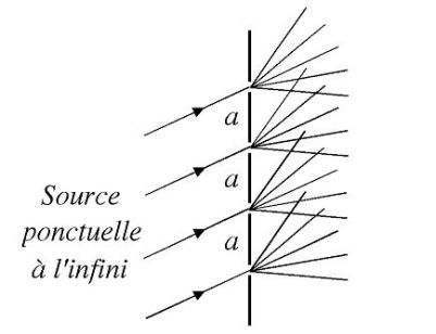
The rays from different slits interfere with each other.
We consider only the interference at infinity.
Note :
The surface of a CD or DVD is formed of small repeating units and substantially constitutes a network.
It is noted that this surface separates white light and appears colored differently depending on the orientation of the disc.
Fondamental : Basic Theory Network
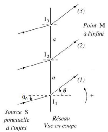
\(S\) is a point and monochromatic source, at infinity, which sends a beam of parallel light and entering the network under the angle of incidence \(\theta_0\).
We seek directions identified by the angle \(\theta\) where the intensity of the rays that interfere at infinity is maximum.
There is interference at infinity among all diffracted rays in the direction \(\theta\).
The amplitude diffracted by the grating at infinity results in interference between the rays from all the illuminated units : this is called interference of \(N\) waves (in the case of Young's slits, it is interference of two waves).
The path difference between the two rays \((1)\) and \((2)\) is :
\(\delta = {(SM)_1} - {(SM)_2} = a\sin \theta - a\sin \theta_0 = a(\sin \theta - \sin \theta_0)\)
(Be careful ! Angles \(\theta_0\) and \(\theta\) can be very large ; we are not in the Gauss conditions, there is no lens !)
The rays are in phase if :
\(\delta \,{\kern 1pt} ({\rm{M}}) = m{\lambda _0}\;\;\;\;(m\;in\;{\rm Z})\)
If the optical path difference between the rays \((1)\) and \((2)\) is \(m\lambda_0\) :
The optical path difference between the rays \((2)\) and \((3)\) applies \(m\lambda_0\).
The optical path difference between the rays \((1)\) and \((3)\) is \(2m\lambda_0\).
All rays that interfere at infinity in \(M\) are in phase : there is maximum light in the direction of the angle \(\theta\).
For a given angle of incidence \(i\), angles \(\theta\) corresponding to maximum light (interference between waves from two successive patterns are constructive) are given by the relation ( "formula of networks") :
\(a(\sin \theta - \sin \theta_0) = m{\lambda _0}\;\;\;\;so\;\;\;\;\sin \theta - \sin \theta_0= m\frac{{{\lambda _0}}}{a}\)
\(m\) is called the order of the spectrum (that is the order of interference).
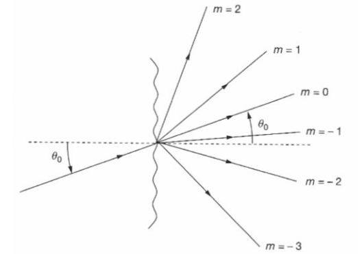
Note that, for a given angle \(\theta_0\), the number of values of \(m\) is limited as \(sin\theta\) is from \(-1\) and \(+1\).
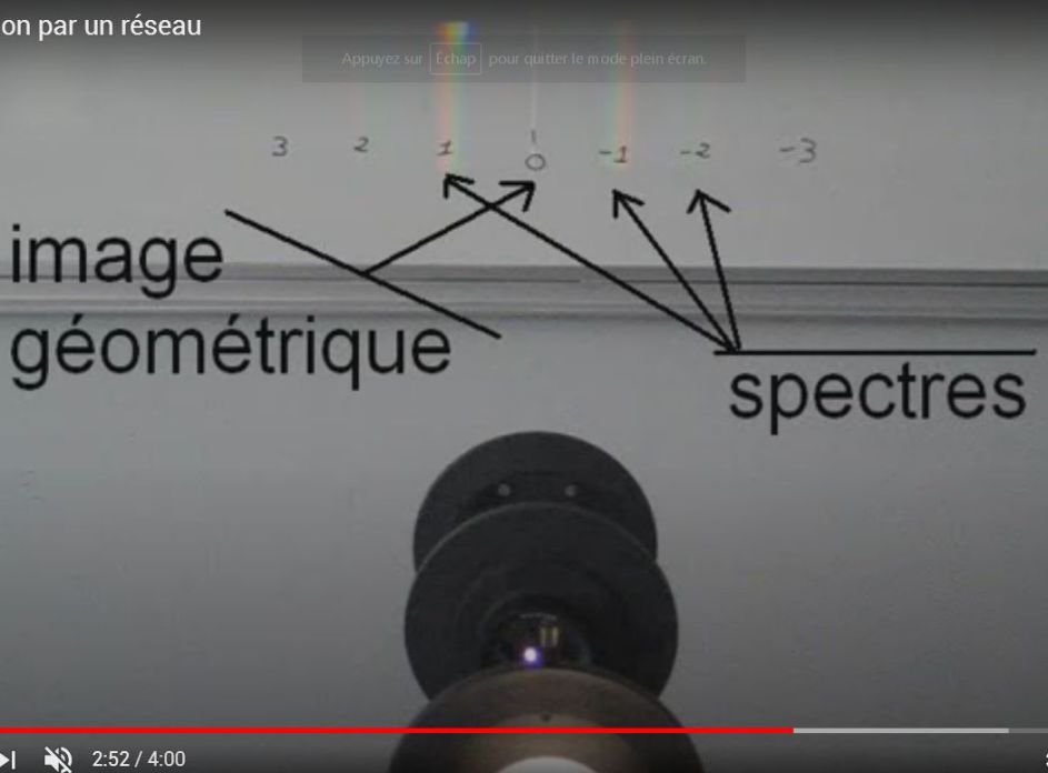
For \(m = 0\), the formula of networks gives \(\theta = \theta_0\) : this solution is in the direction of geometrical optics.
Other solutions can be obtained numerically and depend on the wavelength.
They are represented in figure.
The incident beam can be observed at the output of the network, in several directions.
Accurate measurement of the directions of diffracted rays allows to deduce the wavelength of the radiation used, if the step is known : the system will be a spectrometer.
Knowledge of the wavelength allows access to the step of the grating.
Fondamental : The case of white light
The solution in the direction of geometrical optics :
\(\theta = \theta_0\) (for \(m=0\))
is independently available of the wavelength.
In this direction,white light will be observed.
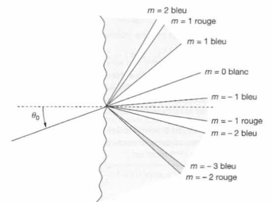
In contrast, in the other orders, the angle \(\theta\) is a function of the wavelength.
This means that according to its color, the ray emerges from the network with a different angle.
As well as the prism, the network disperses the light in the non-zero orders.
The zero order, which corresponds to the direction of geometrical optics, is non-dispersive.
For a given order \(m\), the deviation increases from blue to red.
Orders may sometimes overlap (an order begins when the previous is not complete) : this is the case here for orders \(m = - 2\) and \(m = - 3\).
Exemple : An example of the network
A network including \(n = 800\) units per millimeter is illuminated by an atomic vapor lamp at normal incidence.
The wavelengths are between \(\lambda_{min}=404,7\; nm\) (violet) and \(\lambda_{max}=579,1\;nm\) (yellow).
Do the orders overlap and if so, from what order ?
Assessing deviations extreme wavelengths in different orders through the formula of networks.
The step is given by :
\(a=1/n=1,25.10^{-3}\;mm\)
We can deduce :
\(m=1\) | \(m=2\) | \(m=3\) | |
Violet | \(18,9°\) | \(40,4°\) | \(76,2°\) |
Yellow | \(27,6°\) | \(67,9°\) | // |
Yellow does not exist in order \(3\).
The orders do not overlap.