The Michelson configuration "air blade" ("lame d'air", in french)
Fondamental : Description of the Michelson interferometer
A source \((S)\) is placed at the focus of a collimator lens \((L')\).
The beam from \((S)\) is divided into two by the semi blade - reflective (\(\Sigma\)), called separator.
It is then sufficient to overlap the transmitted and reflected rays through two mirrors.
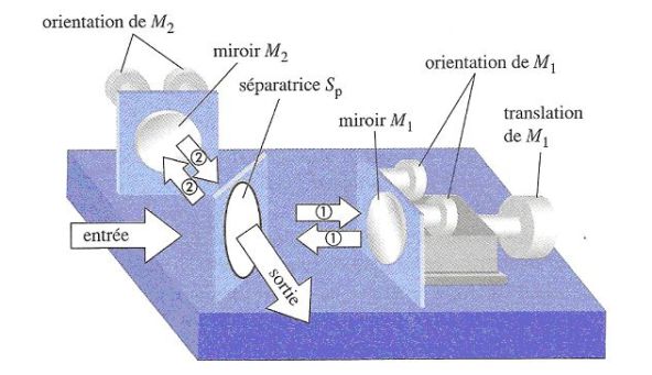
The mirror \((M_2)\) is fixed and the other \((M_1)\) is mounted on a movable carriage.
The orientation of the mirrors can be adjusted by rotation about a vertical axis and a horizontal axis.
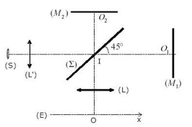
Observation can be done through a projection lens onto a screen \((E)\).
It is called "amplitude division".
It may be mentioned that the Michelson interferometer is used to measure macroscopic distances at a wavelength near fraction, to determine indices (by interposition of a known thickness of blade on one of the "arms" of interferometer), solve a doublet as that of sodium, ...
Fondamental : Equivalent circuit diagram in the case of the air blade
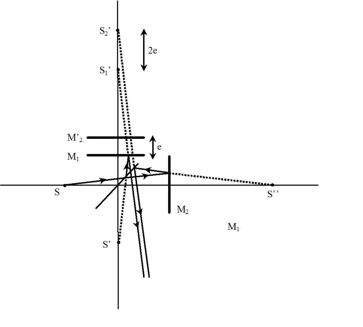
It is as if we could put the source \((S)\) in \((S ')\) (its symmetrical to the splitter) and study the propagation of coming rays \((S')\) through the two mirrors \((M_1)\) and \((M'_2)\), symmetrical \((M_2)\) relative to the splitter.
Fondamental : Using in air blade; equal inclination fringes
In this case, the real mirrors \((M_1)\) and \( (M_2)\) are mutually perpendicular and, therefore, the mirrors \((M_1)\) and \((M'_2)\) are parallel.
We reason in the figure below :
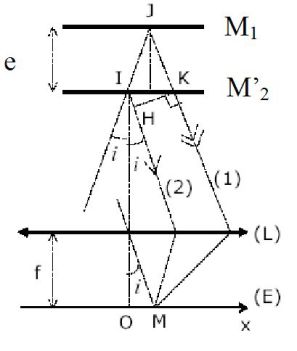
Because of the extent of the source, the studied rays make an angle \(i\), which remains very weak, with the axis of the system.
In this figure, the splitter is not shown because it is assumed perfectly settled and do not introduce any phase shift.
The real and virtual mirror is constituted of an air blade of the parallel surfaces, hence the name of this type of setting.
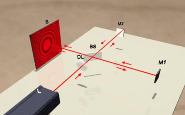
It is noted that the rays \((1)\) and \((2)\) are released parallel.
So they will interfere at infinity which is the place of fringe location : you can watch them on a screen placed in the focal plane of a lens.
Calculating the path difference :
According to the theorem of Malus :
\(\delta = {(SM)_2} - {(SM)_1} = (S{'_2}H) = 2e\cos i\)
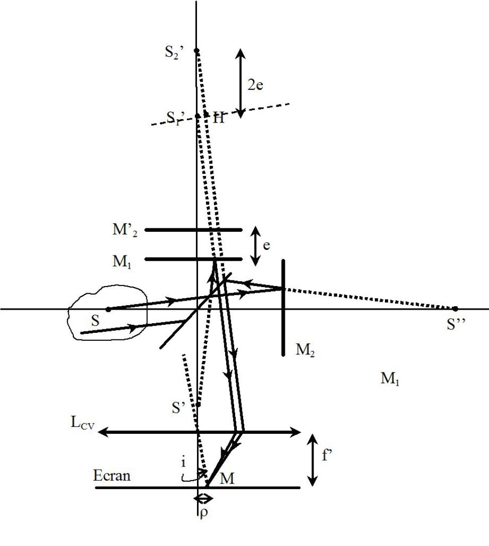
With \(\rho=if'\) :
\(\delta \approx 2e\left( {1 - \frac{{{i^2}}}{2}} \right) = 2e\left( {1 - \frac{{{\rho ^2}}}{{2f{'^2}}}} \right)\)
Light intensity and radius of the rings :
The light intensity is :
\(E(x) = 2{E_{\max }}\left[ {1 + \cos \frac{{2\pi }}{{{\lambda _0}}}2e\left( {1 - \frac{{{\rho ^2}}}{{2f'}}} \right)} \right] \)
The shape of the fringes is given by \(E(M) = cste\), so \(\rho = cste\) : the fringes are rings of the center O (for a source with rotational symmetry).
As these fringes correspond to a fixed angle \(i\) (angle at which we see a point of the source from the center of the collimating lens \((L ')\)), the one that said we observed "equal inclination fringes".
(At the fringe order \(p\) corresponds to the path difference \(p\lambda_0\) and the angle of inclination \(i\) such that \(cosi=\frac {p \lambda_0}{2e}\), hence the name of equal inclination fringes).
The order of interference at the center is equal to \(p(0)=\frac{2e}{\lambda_0}\) and is therefore any ; if \(p(0)\) is an integer, the figure is a center bright and if \(p(0)\) is a half - integer, it is a black center.
Please note, the order of interference \(p(i)=\frac {2ecosi}{\lambda_0}\) decreases if it is further away from the center (the opposite in the case of Young slits).
One ring corresponds to a fixed order of interference. If we decrease the distance\(e\), \(cosi\) will increase, the angle \(i\) will decrease and the rings will shrink and disappear by the center ; correspondingly, the \(K^{ieme}\) ring radius (bright for example) visible on the screen increases. We will see fewer and fewer rings on the screen.
On the screen, the fringes are concentric rings of center O. The radius of the ring of order \(p\) is:
\({\rho _p} = if'\)
With :
\(\cos i \approx 1 - \frac{{{i^2}}}{2} = \frac{{p{\lambda _0}}}{{2e}}\)
If we denote \(p_0=\frac {2e}{\lambda_0}\) the order of interference at the center of the figure (maximum for \(i = 0\)), then :
\(\cos i \approx 1 - \frac{{{i^2}}}{2} = \frac{p}{{{p_0}}}\;\;\;\;\;\;so\;\;\;\;\;\;i = \sqrt {\frac{{2({p_0} - p)}}{{{p_0}}}}\)
Finally :
\({\rho _p} = \sqrt {\frac{{2({p_0} - p)}}{{{p_0}}}} \;f'\)
The intensity at the center is assumed to be maximum, that is to say that \(p_0=\frac {2e}{\lambda_0}\) is an integer.
The first ring of maximum intensity has the order of interference :
\(p=p_0-1\)
Its radius is:
\({\rho _1} = \sqrt {\frac{2}{{{p_0}}}} \;f'\;\;\;\;\;\;(with\;:\;{p_0} = \frac{{2e}}{{{\lambda _0}}})\)
The radius of the \(K^{ieme}\) visible ring (not to be confused \(K\) with the order of interference \(p\)) is :
\({\rho _p} = \sqrt {\frac{{2K}}{{{p_0}}}} \;f'\; = \sqrt K \;{\rho _1}\)
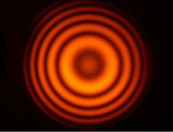
The following figures correspond to the observation in monochromatic light (in the focal plane of a lens of focal distance \(f'=1\;m\)) of equal inclination rings.
The observation area is a square of side \(20\) \(cm\), centered on the figure of interference.
Orders interference at the center were chosen as follows : \(p_0 = 500\), \(1\;000\), \(2\;000\) and \(4\;000\).

The number of rings in the observation field is as big as the order of interference at the center is important, so that the thickness of the blade of the parallel faces is important.
Experimental determination of the order of interference at the center and of the thickness \(e\) of the air blade with parallel faces :
Take the example of the first photograph, for which the \(3rd\) dark ring radius is \(\rho_3=10\) \(cm\).
Thus :
\({\rho _{3,dark}} = \sqrt {\frac{{2({p_0} - ({p_0} - 2,5)}}{{{p_0}}}} \;f' = \sqrt {\frac{5}{{{p_0}}}} \;f'\;\;\;\;\;\;so\;\;\;\;\;\;{p_0} = \frac{{5f'}}{{\rho _{3,dark}^2}} = 500\)
We do find the expected value ; the thickness \(e\) is deduced (given \(\lambda_0=560\) \(nm\)) :
\({p_0} = \frac{{2e}}{{{\lambda _0}}}\;\;\;\;\;\;and\;\;\;\;\;\;e = \frac{{{p_0}{\lambda _0}}}{2} = 0,14\;mm\)
Optical contact (solid color) :
When \(e\) tends to zero, the order of interference tends to zero and the intensity is everywhere \(4E_{max}\) : the intensity on the screen is uniform.
We say we achieved the optical contact and achieved solid color.