Michelson configuration "air corner" ("coin d'air", in french)
Fondamental :
The interferometer is set to air blade with a broad source and one takes the optical contact.
At this time, the changing orientation of one of the two mirrors of a very small angle \(\alpha\) (of the order of magnitude of \(10^{-4}\) \(rad\)).
The configuration obtained by "air corner".
We work in the case of a wide source.
We will reason on the equivalent scheme using the image of the mirror \((M_2)\).
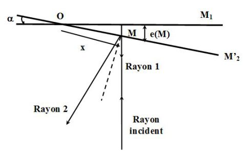
We place at normal incidence. The ray \((1)\) restarts in its initial direction and the ray \((2)\) is reflected symmetrically with respect to the normal of the mirror \((M'_2)\).
The two beams interfere at \(M\), at the mirror \((M'_2)\) : the interference are located at the air corner.
The path difference between the two rays is :
\(\delta = 2e(M) \approx 2\alpha x\)
Where \(e(M)\) is the thickness of the air coner at the point \(M\) and \(x\) the abscissa of \(M\).
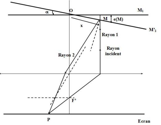
Indeed, if we place a lens (or the eye) for observing fringes of the air corner located on the mirror \((M'_2)\), then the optical path difference between the two beams that interfere at the point \(P\) of screen (not in the image focal plane of the lens !) is equal to \(\delta = 2e(M) \approx 2\alpha x\) (use the principle of inverse return of light and the property of stigmatism).
Given the fact that the mirror \((M'_2)\) is inclined relative to the mirror \((M_1)\), one loses the invariance property by rotation around the normal to \((M_1)\).
The interference fringes will be straight.
The condition for a bright fringe is :
\(\delta = 2\alpha x = p{\lambda _0}\)
So :
\(x = \frac{{{\lambda _0}}}{{2\alpha }}p\;\;\;\;\;\;\left( {{\rm{p \;integer}}} \right)\)
The shape of the fringes is given by \(p(x) = cste\), so \(x = cste\) : fringes are straight, parallel to the edge of the dihedral formed by the mirrors.
Since the illumination is constant for a constant distance \(e(x)\) between the mirrors, it is observed that said "equal thickness fringes".
We can calculate the inter-fringe that is :
\(i = \frac{{{\lambda _0}}}{{2\alpha }}\)
Thus the interfringe increases when the angle \(\alpha\) between the two mirrors decreases.
This fact is used when one wants to transfer from an interferometer mounted in air corner to an interferometer mounted in air blade : simply rotate one of the mirrors in the direction that increases the interfringe to reduce and gradually reach a zero \(\alpha\) angle
The interfringe is proportional to \(\lambda_0\), each wavelength gives its own system of fringes, from which a temporal coherence problem, except in the vicinity of the edge where the path difference is zero, regardless of the wavelength.
Complément : Observation of fringes of equal thickness
The fringes, localized in the interferometer in the vicinity of mirrors, can be directly observed on a screen.
A mirror \((M_1)\) projection is performed on a screen at a distance \(D\) using a thin convergent lens \((L_2)\) of focal distance \(f'_2\) (typically, \(20\) \(cm\)).
The screen is in any case not in the lens focal plane \((L_2)\).
Is recalled that with a convergent lens of focal length \(f'\), the minimum distance between an object and its image is \(4f'\) (typically, \(80\) \(cm\)).
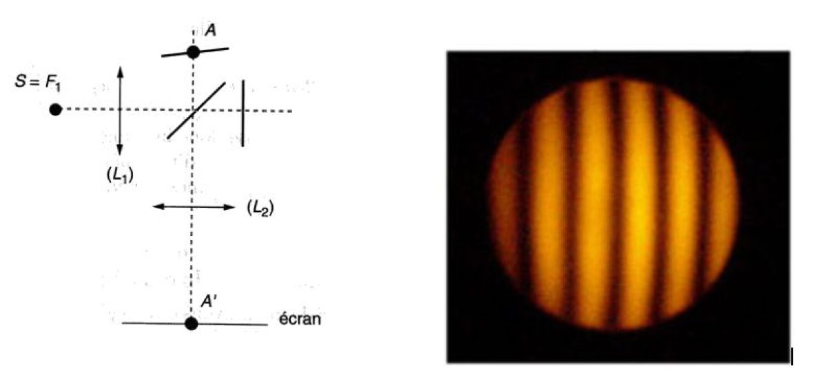
On the other hand, to illuminate the air wedge under quasi-normal incidence, the source is located at the focus of a converging thin lens \((L_1)\) of short focal length (of the order of \(10\;cm\)).
The interfringe \(i_{screen}\) measured experimentally on the screen is then connected to the real interfringe \(i\) by the optical magnifying \(\gamma\) of the projection :
\(i_{screen}=\gamma i\)
We recall according to the relationship of Descartes, with usual notations :
\(- \frac{1}{{\overline {OA} }} + \frac{1}{{\overline {OA} '}} = \frac{1}{{f'}}\;\;\;\;\;and\;\;\;\;\;\gamma = \frac{{\overline {A'B'} }}{{\overline {AB} }} = \frac{{\overline {OA'} }}{{\overline {OA} }}\)
Measuring the interfringe may allow a measurement of \(\lambda_0\) or of the angle \(\alpha\).
Numerically, for fringes visible to the naked eye, one must have typically \(i_{screen}>1\) \(mm\), either with a magnification of the order of \(10\), \(i>0,1\) \(mm.\).
With \(\lambda_0 \approx 600\) \(nm\), we obtain \(\alpha<3.10^{-3}rad\).
In practice, the angle between the mirrors must be very small.
Remarque : Some general remarks on the air corner
Current observation : in everyday we easily observe the interference of equal thickness that often iridescent.
(Iridescence : property of certain substances to disperse colored rays into light as the rainbow) :
A thin layer of oil on wet asphalt makes them appear.
We meet them on the surface of a soap bubble.
By pressing two glass plates against one another and that they imprison some dust, forming a variable thickness air blade.
What emerges is of equal thickness fringes.
Adjust more or less the blades and you distort the fringes.
Applications :
Control surfaces by interferometry (measurement of low thicknesses, vibration of surfaces, ...) is based on the observation of equal thickness fringes.
They will reach a precise control of the surface state of the order of a tenth of a micron.
Study of contact microphone - drops or vesicles on a substrate by interference microscopy.
