Experience of Young's slits
Fondamental : The device of Young holes (without lenses)
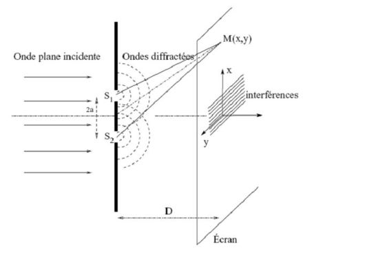
In the device of Young holes, the main source \((S)\) is located on the segment of the mediator joining the two secondary sources.
Interference is observed on a screen \((E)\) parallel to the axis of the two sources.

Since the interference is visible on the screen independently of its position, it is called non-localized interference throughout the space.
In practice, \(D>>a\) -see figure) and it will be observed fringes at points \(M\) of coordinates \((x,y)\) closed to \(O\), for which \(x\) and \(y<<D\).
The optical path difference between the rays \((2)\) and \((1)\) is equal to (the rays propagate in the air, index is practically equal to \(1\)) :
\({\delta _{2/1}} = (S{S_2}M) - (S{S_1}M) = ({S_2}M) - ({S_1}M) = {S_2}M - {S_1}M\)
Is :
\({\delta _{2/1}} = \sqrt {{D^2} + {{(x + \frac{a}{2})}^2} + {y^2}} - \sqrt {{D^2} + {{(x - \frac{a}{2})}^2} + {y^2}}\)
We do the expansion limited at the second order in \(a/D\), \(x/D\) and \(y/D\) :
\({\delta _{2/1}} = D{\left( {1 + {{(\frac{x}{D} + \frac{a}{{2D}})}^2} + {{\frac{y}{{{D^2}}}}^2}} \right)^{1/2}} - D{\left( {1 + {{(\frac{x}{D} - \frac{a}{{2D}})}^2} + {{\frac{y}{{{D^2}}}}^2}} \right)^{1/2}}\)
And so :
\({\delta _{2/1}} = D{\left( {1 + (\frac{{{x^2}}}{{{D^2}}} + \frac{{{a^2}}}{{4{D^2}}} + \frac{{ax}}{{2{D^2}}}) + {{\frac{y}{{{D^2}}}}^2}} \right)^{1/2}} - D{\left( {1 + (\frac{{{x^2}}}{{{D^2}}} + \frac{{{a^2}}}{{4{D^2}}} - \frac{{ax}}{{2{D^2}}}) + {{\frac{y}{{{D^2}}}}^2}} \right)^{1/2}}\)
Is :
\(\delta _{2/1} = D( {1 + \frac{1}{2}(\frac{{{x^2}}}{{{D^2}}} + \frac{{{a^2}}}{{4{D^2}}} + \frac{{ax}}{{2{D^2}}}) + \frac{1}{2}{{\frac{y}{{{D^2}}}}^2}}) - D( {1 + \frac{1}{2}(\frac{{{x^2}}}{{{D^2}}} + \frac{{{a^2}}}{{4{D^2}}} - \frac{{ax}}{{2{D^2}}}) + \frac{1}{2}{{\frac{y}{{{D^2}}}}^2}})\)
Finally :
\({\delta _{2/1}} = \delta = \frac{{ax}}{D}\)
And the illumination at point \(M\) becomes :
\(I(M) = 2{I_0}\left[ {1 + \cos \left( {\frac{{2\pi }}{{{\lambda _0}}}\frac{{ax}}{D}} \right)} \right]\)
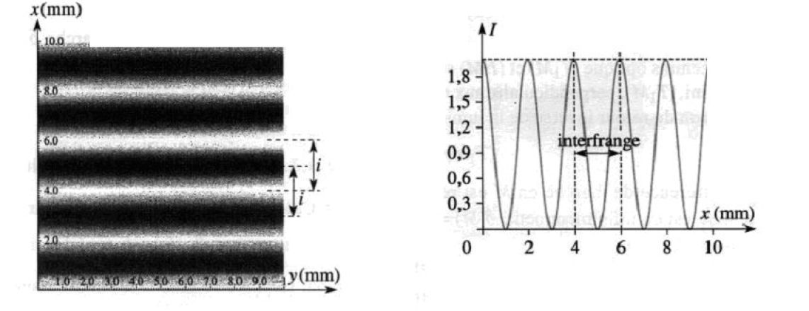
The interference fringes are obtained by \(x=constante\) and thus are straight lines parallel to the axis (Oy).
Fondamental : Inter-fringe
On the screen, the fringes of the same nature will be separated by a distance called inter-fringe and denoted \(i\), which is ultimately the spatial period of cosine which is involved in the intensity :
\(I(M) = 2{I_0}\left[ {1 + \cos \left( {\frac{{2\pi }}{{{\lambda _0}}}\frac{{ax}}{D}} \right)} \right]=2{I_0}\left[ {1 + \cos \left( {2\pi\frac{x}{i}} \right)} \right]\)
So :
\(i = \frac{{{\lambda _0}D}}{a}\)
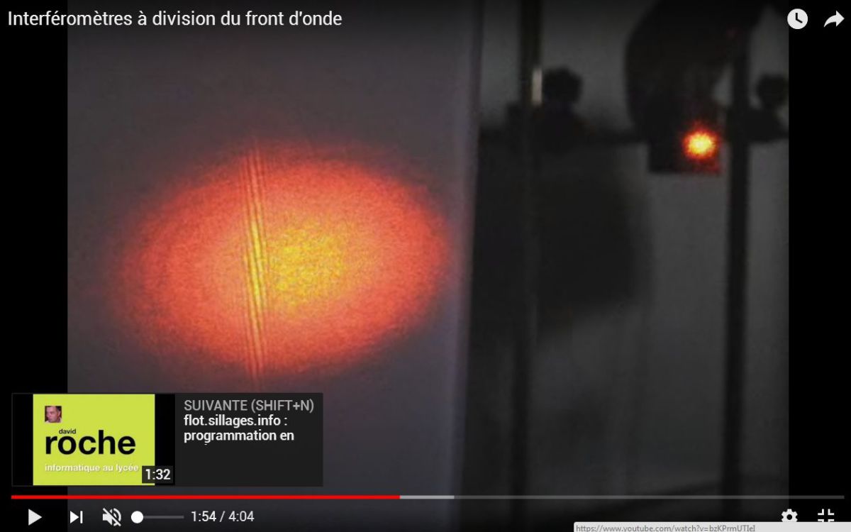
With holes gape of \(a=1\) \(mm\), diameter of \(1/10\) \(mm\), and a screen placed at \(1\) \(m\), a dozen fine fringes are discernible at the center of a diffraction pattern.
\((S)\), \(S_1\) and \(S_2\) holes may be replaced by slits (very narrow along Ox) parallel to Oy ; indeed, the atoms (in different positions) of the source located behind the slit \((S)\) emit incoherent wave trains together.
One can thus summing the illuminations on the screen due to each of these atoms.
The illumination is not dependent on variable \(y\), the luminous intensities will build without blur : the phenomenon will be brighter.
\(D\) is of the order of magnitude of the meter, \(a\) millimeter and \(\lambda_0\) micrometer ; the inter-fringe \( i\) is in the order of the millimeter.
Thus for the first time, Thomas Young in \(1804\) could measure the wavelengths of light radiation.
Fondamental : Installation of Young's holes with lenses
The classical installation of Young's holes can be improved.
Indeed, the interfering rays at a point \(M\) of the screen does not have the same intensity.
When passing through a hole, diffraction "spreads" the wave in a cone around the direction of geometrical optics.
The diffracted rays in different directions have no reason to have the same intensity.
The contrast of interference is then not maximal.
Moreover, the most illuminated areas by each hole badly overlap and interference phenomenon is little luminous.
It overcomes these disadvantages by adding two lenses to the device.
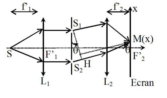
The point source \((S)\) is placed at the focus of a CV lens \((L_1)\) and put the screen in the focal plane of another CV lens \((L_2)\).
To draw the figure proposed above, it is necessary to start from a point \(M\) of the screen and give a ray "construction" which passes through the center of the second lens and inclined at an angle \(\theta\) to the optical axis.
The rays that interfere in \(M\) have much the same intensity as they are inclined at the same angle \(\theta\) to the horizontal, which is the direction of propagation of geometrical optics.
The phenomenon is bright around \(x = 0\) (it is the image of geometrical optics).
Determining the path difference :
\(\delta = {(SM)_2} - {(SM)_1}\)
\((S_1)\) and \((S_2)\) holes belong to the same wave surface : the two waves arrive in phase at the holes. Consequently :
\((SS_1) = (SS_2)\)
Therefore :
\(\delta = ({S_2}M) - ({S_1}M)\)
The principle of inverse return of light and Malus' theorem can be concluded that :
\(({S_1}M) = (HM)\)
Therefore :
\(\delta = ({S_2}H) = {S_2}H\)
The angle \(\theta\) is small and if \(a\) denotes the distance between the two sources :
\(\delta = {S_2}H \approx a\theta = \frac{{ax}}{{f{'_2}}}\)
And the illumination in the focal plane of the second lens :
\(I(x) = 2{I_0}\left( {1 + \cos \left( {2\pi \frac{{ax}}{{{\lambda _0}f{'_2}}}} \right)} \right)\)
The result is similar to that obtained without lens.
Distance holes - screen is replaced by the focal length of the \(2nd\) lens.
The fringes are rectilinear and of course the inter-fringe \(i\) is :
\(i = \frac{{{\lambda _0}f{'_2}}}{a}\)