Self-inductance, mutual inductance
Définition : Self-inductance
A closed wire loop \((C)\) is travelled by an intensity \(I\).
Its own magnetic field \(\vec B_p(M)\), which is given by , is proportional to \(I\).
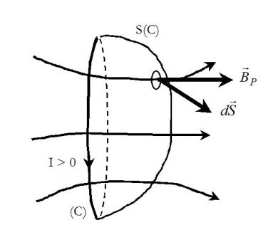
The flux of the proper magnetic field through an outline which is oriented in the positive direction of the chosen current, is also called “own flux”.
It is proportional to \(I\) :
\({\Phi _P} = \iint_{(S)}{\vec B_P}.d\vec S \propto I\;\;\;\;\;\;\;so\;\;\;\;\;\;\;{\Phi _P} = LI\)
The coefficient \(L\) depends on the geometric characteristics of the circuit only.
It is called the self-inductance of the circuit \((C)\).
Sign of \(L\) :
If \(I>0\), the magnetic field has the direction represented on the figure.
Its flux is positive so \(L>0\).
Si \(I<0\), direction of the magnetic field changes and the flux is negative.
Hence, \(L\) is a positive coefficient.
The unit of the flux is Weber and the unit of the inductance is Henry.
Attention : Self-induction of a wire circuit
\({\Phi _P} = \iint_{(S)}{\vec B_P}.d\vec S \propto I\;\;\;\;\;\;\;so\;\;\;\;\;\;\;{\Phi _P} = LI\)
Exemple : Self-inductance of a solenoid
The magnetic field inside an infinite solenoid is :
\(\vec B = \mu_0 n I \;\vec u_z\)
The proper flux through \(N\) wire loops occupying a given length \(\ell\) is : (\(n=N/\ell\))
\(\Phi_P=(\mu_0\frac{N}{\ell}I)NS=LI\)
Hence the self-inductance :
\(L=\frac{\mu_0 N^2S}{\ell}\)
Order of magnitude :
For a coil of length \(10\;cm\), formed of \(100\) whorls and which has a diameter of \(1\;cm\), the self-inductance is around \(0,01\;mH\) : Henry is a pretty big unit.
Bigger Self-inductances can be obtained by iron-core coils.
But the equation that gives \(L\) is more complicated (\(L\) not only depends on the geometry of the circuit but also on the intensity).
Exemple : Self-inductance of a torus coil of rectangular section
A torus coil has a rectangular section of height \(h\) and radii \(a\) and \(b\).
It contains \(N\) joined whorls travelled by intensity \(I\).
Any meridian plane is a plane of symmetry.
In any point of this plane, in cylindrical coordinates, the proper field is ortho-radial and depends on \(r\) and \(z\) :
\(\vec B_P(M)=B_P(r,z) \;\vec u_{\theta}\)
The field lines are circles around \((Oz)\) axis.
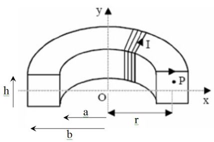
Ampere's circuital law applied to a field line of radius \(r\) :
\(2\pi \;r\;B_P(r,z) = {\mu _0}NI\;\;\;\;\;\;\;so\;\;\;\;\;\;\;{B_P}(r) = \frac{{{\mu _0}NI}}{{2\pi }}\frac{1}{r}\)
The field actually does not depend on \(z\).
Its own field through the \(N\) whorls is :
\({\Phi _P} = N\left( {\int_{\;a}^{\;b} {} {B_P}(r)\;hdr} \right) = \frac{{{\mu _0}{N^2}I}}{{2\pi }}h\;\ln \left( {\frac{b}{a}} \right)\)
Hence the inductance :
\(L = \frac{{{\mu _0}{N^2}h}}{{2\pi }}\;\ln \left( {\frac{b}{a}} \right)\)
Définition : Mutual Inductance
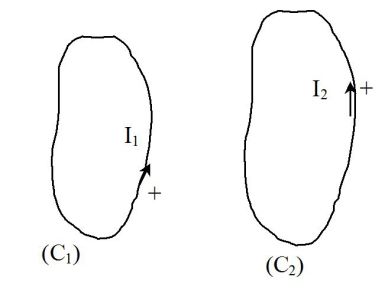
Two wire circuits \((C_1)\) and \((C_2)\) are travelled by intensities \(I_1\) and \(I_2\).
The flux of the magnetic field \(\vec B_2\) through the closed outline \((C_1)\) oriented by the positive direction of current \(I_1\) is proportional to \(I_2\) :
\(\Phi_{2->1}=MI_2\)
Likewise, the flux of the magnetic field \(\vec B_1\) through the closed outline \((C_2)\) oriented by the positive direction of \(I_2\) is proportional to \(I_1\) :
\(\Phi_{1->2}=MI_1\)
\(M\) is the mutual inductance of these two circuits.
Unlike the inductance, which is always positive, \(M\) can be positive or negative, depending on the orientation of the circuits.
Remark :
If \(\Phi_{1->2}\) can be calculated, \(M\) and \(\Phi_{1->2}\) can be deduced.
Sometimes, one of the two fluxes is hard to calculate whereas the other one is easier.